

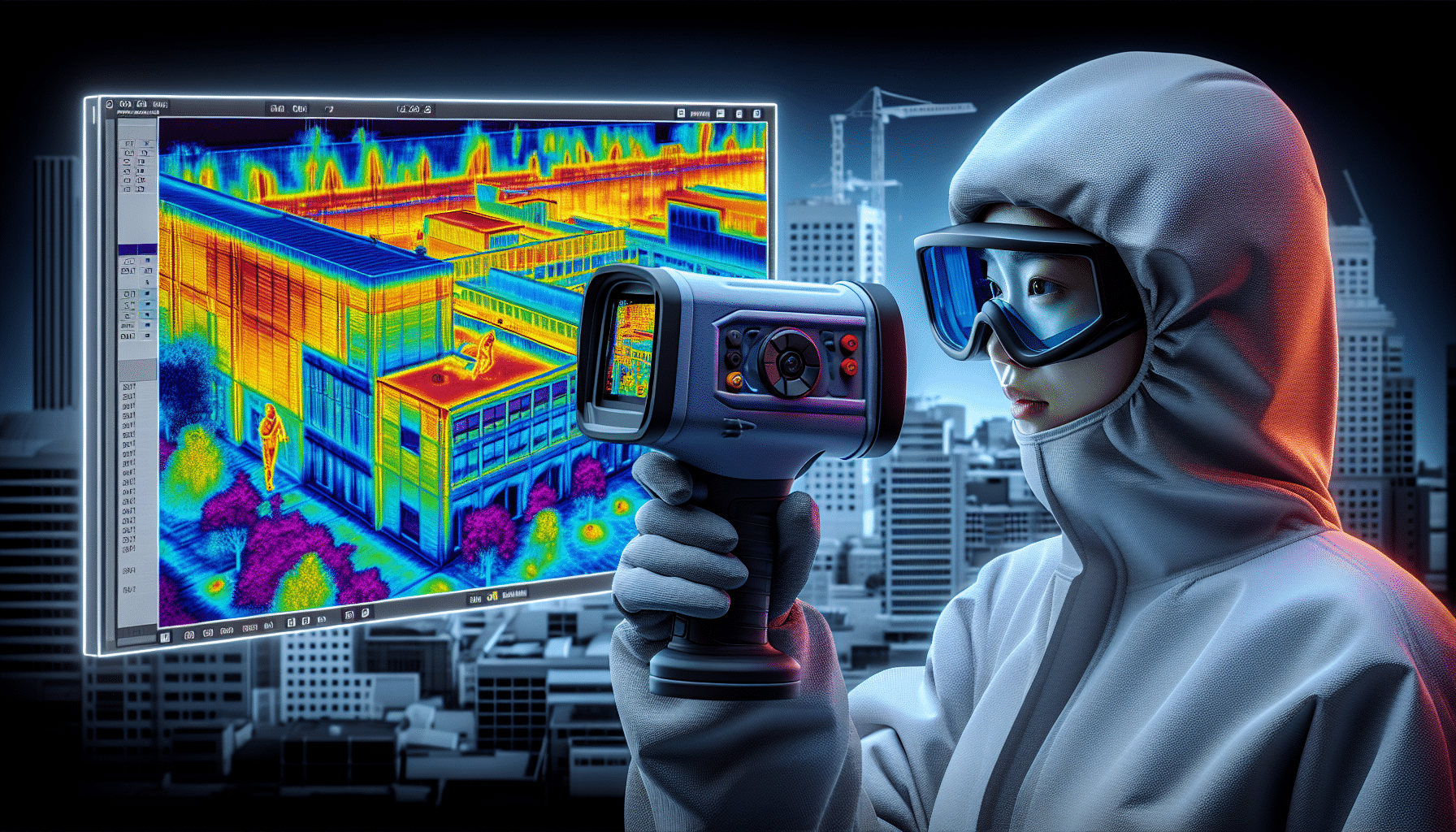
For Hidden Thermal Bridges: Perform Infrared Thermal Imaging
In Dubai’s extreme climate, where air conditioning runs constantly, hidden thermal bridges silently drain energy and foster mould growth. Learning How to Perform infrared thermal imaging for hidden thermal bridges empowers building professionals to detect these issues non-invasively. This guide provides a complete, actionable tutorial tailored to UAE conditions like high humidity and thermal bridging at wall-floor junctions.
Thermal bridges occur where heat flows faster through materials like concrete slabs or metal fixings, creating cold spots that condense moisture—common in rapid UAE construction. By mastering how to perform infrared thermal imaging for hidden thermal bridges, you can verify insulation, support post-remediation checks, and optimise building performance. Let’s dive into the process[1][5].
Understanding How to Perform Infrared Thermal Imaging for Hidden Thermal Bridges
Infrared thermal imaging captures surface temperature variations using cameras sensitive to infrared radiation emitted by objects. When learning how to perform infrared thermal imaging for hidden thermal bridges, recognise that thermal bridges appear as linear anomalies—warmer in winter scans from inside, colder in summer from outside[2][4].
In UAE villas, these bridges often form at balcony penetrations or skirting board junctions due to concrete’s high conductivity. Passive thermography relies on natural differentials like AC cooling (20°C indoors vs 45°C outside), while active uses heaters for precision[1][5]. This method aligns with my experience at Saniservice, where we’ve mapped bridges causing hidden mould in Dubai residences.
Equipment Needed for How to Perform Infrared Thermal Imaging for Hidden Thermal Bridges
Start with a high-resolution infrared camera (320×240 pixels minimum, ideally FLIR or similar with ±2°C accuracy). Include a tripod for steady shots, laser pointer for spot measurements, and software like FLIR Tools for analysis[7][9].
For UAE pros, add humidity/temperature data loggers (e.g., measuring 40-60% RH) and protective gear for dusty sites. Budget: AED 15,000-50,000 for entry-level kits. Essential accessories: reflective markers and notepad for annotations[4].
Camera Specifications
- Thermal sensitivity: <0.05°C for subtle bridges
- Field of view: 25° lens for walls, wide-angle for rooms
- Emissivity adjustment: 0.95 for concrete, 0.9 for plaster
Preparation Steps Before Performing Infrared Thermal Imaging for Hidden Thermal Bridges
Timing is critical: Scan interiors 4-6 hours after AC startup (delta-T >10°C) or exteriors at dawn/dusk. Stabilise conditions—no recent rain or solar loading. Document ambient: 24°C indoor, 50% RH[2][3].
Clear surfaces of dust or furnishings. In Dubai villas, check for common bridges: slab edges, steel beams, window frames. Brief occupants to avoid doors/windows during scans[5].
8-Step Guide: How to Perform Infrared Thermal Imaging for Hidden Thermal Bridges
Follow these steps precisely to master how to perform infrared thermal imaging for hidden thermal bridges. Each builds on my field protocols at Saniservice for UAE buildings.
- Calibrate Camera: Power on, set emissivity (0.95 concrete), distance-to-spot ratio (ensure <1m accuracy). Auto-adjust gain for dynamic range[7].
- Establish Baseline: Scan uniform wall 2m away, note average temperature (e.g., 22°C). Mark grid lines every 1m for reference[4].
- Select Scan Direction: Start low (floor junctions), move up. Hold camera perpendicular, 1-3m distance, overlap images 20%[1][2].
- Capture Passive Data: In AC-cooled rooms, cold bridges show as warmer lines (e.g., 4°C above surround). Take 30s videos for airflow patterns[9].
- Apply Active Heating (Optional): Use 500W halogen lamp 1m away for 5-10 mins on suspect areas. Re-scan for enhanced contrast[2].
- Record Visuals: Pair each thermal image with visible photo. Note GPS or room labels[3].
- Multi-Angle Scans: Repeat from corners, overhead if ceilings involved. Focus on junctions: wall-floor, lintels[5].
- Log Data: Export radiometric JPEGs with spot temps. Flag anomalies >3°C differential[4].
Interpreting Results When You Perform Infrared Thermal Imaging for Hidden Thermal Bridges
Bridges manifest as linear patterns deviating 3-10°C from surrounds. In summer Dubai scans (interior), cold indoor air makes bridges warmer via conduction from hot exterior[2][4]. Use palettes: iron for high contrast.
Overlay thermal on visual images to correlate—e.g., concrete slab edges glow orange. Quantify: Linear thermal transmittance (ψ-value) via software. Confirm with moisture meters if mould suspected[1][5].
Image alt: “How to Perform Infrared Thermal Imaging for Hidden Thermal Bridges – Thermogram showing linear cold spots at wall-floor junction in Dubai villa.”
Common Pitfalls in How to Perform Infrared Thermal Imaging for Hidden Thermal Bridges
Avoid solar reflection: Wait 3 hours post-sun exposure. Reflections mimic bridges—check angles[9]. Insufficient delta-T (<5°C) hides issues; UAE winters rarely suffice indoors[3].
Misread airflow: Fans create false cools. Emissivity errors on glossy paints skew 5°C. Always validate with calculations or invasive checks[5].
Dubai-Specific Tips for How to Perform Infrared Thermal Imaging for Hidden Thermal Bridges
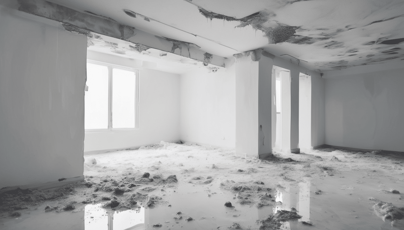
In UAE’s 45°C summers, exterior scans at night reveal slab bridges causing skirting mould—common in Jumeirah villas. AC overcooling (18°C) amplifies indoor deltas[4].
Target gypsum-gypsum board junctions; rapid builds skip thermal breaks. Post-rain (rare but impactful), scan for evaporative cools masking bridges. Costs savings: Fix saves AED 5,000/year AC bills[5].
From experience, thermal bridges at wall-floor in air-conditioned Dubai homes drive 70% hidden mould cases we investigate.
Advanced Applications After Learning How to Perform Infrared Thermal Imaging for Hidden Thermal Bridges
Post-remediation: Re-scan to verify breaks (e.g., aerogel insulation). Integrate with Blower Door tests for air leaks[4]. Architects: Pre-install checks for MEP penetrations.
Software like ThermaCAM analyses ψ-values. Pair with hygrometers for dew point risks in 60% RH[2]. UAE green codes (Estidama) mandate such verification.
Key Takeaways
- Master delta-T timing for clear images.
- Use 8 steps for repeatable results.
- Dubai focus: Night exteriors, AC interiors.
- Validate anomalies quantitatively.
References: FHWA Infrared Thermography[1], InfraredTraining Building Science[4], Schoeck Thermal Bridging Guide[5].
By following this guide on how to perform infrared thermal imaging for hidden thermal bridges, professionals in Dubai and Riyadh can prevent costly energy loss and health risks. Apply today for healthier buildings.
JV de Castro, IAC2
JV de Castro is the Chief Technology Officer at Saniservice, where he leads innovation in indoor environmental sciences, IT infrastructure, and digital transformation. With over 20 years of experience spanning architecture, building science, technology management, digital media architecture, and consultancy, he has helped organizations optimize operations through smart solutions and forward-thinking strategies. JV holds a Degree in Architecture, a Masters of Research in Anthropology, an MBA in Digital Communication & Media, along with certifications in mold, building sciences and advanced networking. Passionate about combining technology, health, and sustainability, he continues to drive initiatives that bridge science, IT, and business impact.

Leave a Reply